

 Chinese
 English
 German
 French
 Russian
 Arabic
 Panjabi

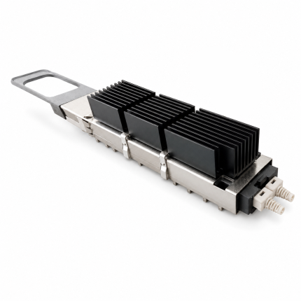
An ELSFP supplies continuous-wave (CW) laser light to optical engines in a co-packaged optics (CPO) system that uses external lasers. ELSFP stands for External Laser Small Form Factor Pluggable. Its job is to provide the light that an optical engine can modulate with data. OIF defines a replaceable, faceplate-pluggable package with a blind-mate optical connection for this role. CPO designs with integrated lasers do not need this external-laser arrangement. See OIF-ELSFP-02.0, introduction and application overview (PDF).
Follow the light path separately from the data path
For a representative externally illuminated CPO transmitter, separate these two paths:
- Light supply: ELSFP laser output → internal optical connection → optical engine.
- Transmit data: host ASIC electrical data → optical-engine modulation → data-bearing optical signal → network fiber.
The optical engine places information onto the supplied light. The ELSFP is therefore a laser-source module, not a complete data transceiver or the optical engine itself. Its CW output should not be confused with the modulated signal at the system’s network port. UL Solutions describes this separation of functions.
For a purchasing specification, identify which of those boundaries the requested item covers. Specify whether the delivery covers the laser source alone, the CPO optical engine or a complete pluggable data-transceiver assembly.
Why separate the laser in an AI data-center system?
CPO places optical engines close to the host ASIC to shorten the high-speed electrical connection. An external-laser architecture can then place the lasers away from the co-packaged assembly’s thermal environment and make the light source separately replaceable. There is a tradeoff: the additional optical path introduces loss that must be included in the design. OIF discusses both integrated and external laser approaches in its Co-Packaging Framework, sections 5 and 7.3.1 (PDF).
External laser source
The light source is separate from the optical engine. An ELSFP implements a replaceable, faceplate-pluggable source; its optical delivery path must be included in the design.
Laser integrated in the engine
The laser is integrated within the optical engine. This arrangement does not use the supply path shown in the external-source diagram.
This explains the relevance to AI infrastructure without making ELSFP a requirement for every AI system. Start with the platform architecture. Do not infer a system’s bandwidth, energy consumption, link reach or service availability from the laser form factor alone.
What the ELSFP designation does not settle
A shared form-factor name is not enough to approve a module for a particular host. OIF-ELSFP-02.0, dated January 8, 2025, includes major mechanical revisions relative to 01.0. Record the exact specification revision and mating-interface drawings in a design review rather than relying on the word “ELSFP.” The OIF implementation-agreement index lists the form-factor and management documents separately.
Likewise, a component datasheet is evidence about that component under its stated conditions. It does not by itself establish that a chosen module, connector assembly, optical engine and host firmware have been qualified together.
A practical ELSFP design-in checklist
Use the following as a working review checklist, not as an OIF compliance test plan. Assign an owner and record the evidence for each item before moving from a candidate module to a platform-approved part.
1. Define the optical-engine input contract
Ask the optical-engine owner to provide the wavelength plan, required inputs, acceptable input-power range and polarization requirements. The deliverable should be an input specification with limits, not just a nominal wavelength or a system data-rate label.
2. Produce one end-to-end interface map
Map each source output to its intended optical-engine input. Attach the connector and keying drawings, fiber assignments and applicable revisions. Have the laser, cable and host teams review the same document; separate drawings can each look correct while describing different connections.
3. Close the optical budget at a named reference plane
State where each power value is specified or measured. Account for the intervening connectors, fiber routing, any splitters and coupling losses. Record both lower and upper limits at the engine input, together with the conditions and margin assumptions. A useful review question is: “Can someone reproduce this budget from the attached drawings and measurement definitions?”
4. Treat electrical and thermal integration as host work
Request the module’s electrical and thermal limits and compare them with the actual host design. Document the intended operating conditions, cooling arrangement and relevant worst-case scenarios. Resolve missing limits with the supplier rather than substituting typical values for acceptance limits.
5. Write the control and fault-response sequence
Decide who enables the source, maps it to engine inputs, reads telemetry and responds to a loss of light. OIF’s management white paper (PDF) recommends host-controller coordination of the external light sources and optical engines; it is informative architectural guidance, not a replacement for the applicable specifications. For your platform, request a documented startup, shutdown and fault-recovery sequence plus a list of the management features actually implemented.
6. Separate replaceability from service continuity and safety
Ask what happens to traffic while a source is unavailable, what dependencies share that source and what the replacement procedure requires. Treat redundancy and interruption-free service as requirements to demonstrate, not consequences of a pluggable package. Separately, review laser safety for the assembled system and its service conditions. A component-level evaluation does not establish the safety of the complete host; UL Solutions explains the distinction. Use an approved laboratory procedure and qualified personnel for optical testing.
7. Define what an evaluation must prove
Before ordering hardware, write the questions the evaluation needs to answer and the evidence that would close each question. Record the exact module revision, fixture, cable, firmware, measurement location and operating conditions with the results. Keep module characterization separate from full-system qualification so a successful bench check is not reported as platform interoperability.
Turn the checklist into a useful supplier inquiry
A concise request for quotation can include:
- The host architecture and optical-engine input specification.
- The proposed module, quantities and requested schedule.
- The connector drawings, fiber map and required document revisions.
- The power-budget reference planes and operating conditions.
- The management requirements and planned evaluation questions.
- Whether the request covers the module alone or also an evaluation board and optical test cable.
For Western Optronics options, use the ELSFP selection guide for the wavelength-configuration comparison and the ELSFP evaluation kit page for the available evaluation documentation. The published product pages cover the CWDM4 ELSFP module and the 1311 nm ELSFP module.
Send your ELSFP requirements to Western Optronics. Request confirmation of the proposed configuration, supplied items and commercial terms. These links identify products and inquiry routes; this article does not assert compatibility with a particular host or report completed qualification testing.